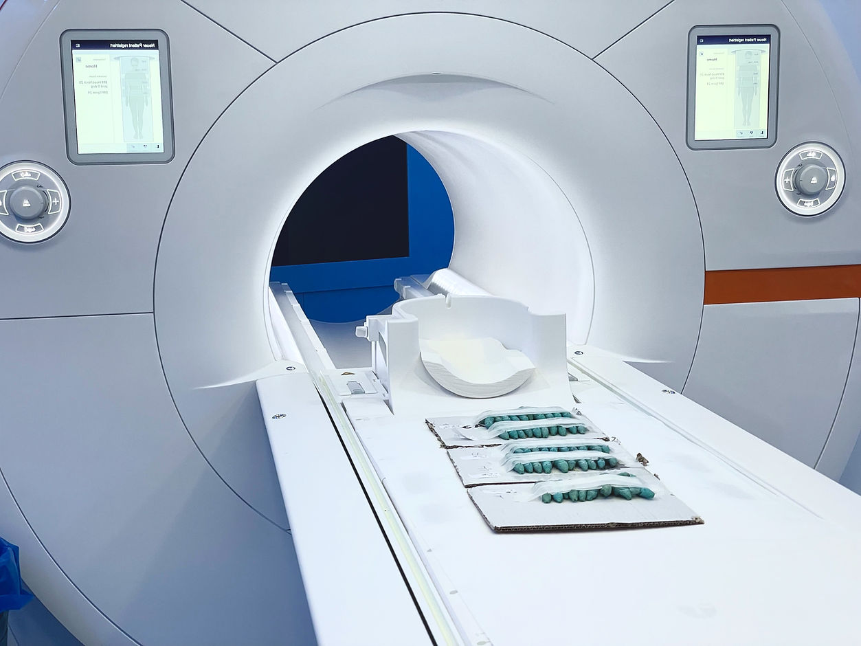
MRT (Magnetresonanztomographie)
Die Magnetresonanztomographie (MRT) ist ein bildgebendes Verfahren, bei dem starke Magnete und Radiowellen dazu genutzt werden, um detaillierte Bilder des Körperinneren zu erstellen. Die MRT eignet sich besonders gut für die Darstellung von Weichteilen wie z. B. dem Darm und bietet einen hervorragenden Kontrast zwischen verschiedenen Gewebetypen.
Vielleicht interessieren Sie sich auch für andere Methoden und Konzepte, die hier vorgestellt werden:
© Anton Windfelder

MAGNETIC RESONANCE IMAGING
This basic introduction on MR imaging will use mostly classical theory and not discuss quantum theory. Therefore, we will use mass, spin angular momentum, and nuclear magnetism concepts to describe MR imaging principles.
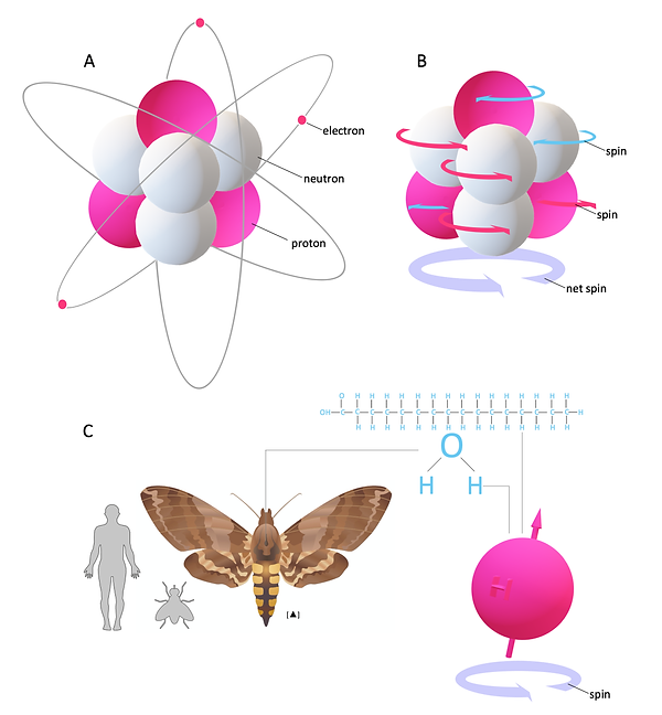
Figure 1: MR active nuclei and spin of 1H
© Anton Windfelder
MR imaging is based on the spinning magnetic motion of specific nuclei within biological tissue and how they interact with external magnetic fields inside the MR scanner (Figure 1A and B). Each nucleon or atom has a spinning motion (spin). In nuclei with an even number of nucleons, these spins cancel each other out. But nuclei with an odd number of nucleons possess a net spin (Figure 1B). These atoms are suitable for MR imaging and are therefore also referred to as MR-active nuclei. Examples for MR-active nuclei are 1H, 13C, 170, and 19F. To keep this introduction manageable, we will focus on 1H (referred to as protons). Hydrogen is the most common atom in biological tissues, abundant in water or fat, and therefore remarkably useful for MR imaging (Figure 1C). Hydrogen has an inherent magnetic field similar to a bar magnet (nuclear magnetism) (Figure 2A and B). Accordingly, protons align their rotational axis (spin) to an external magnetic field B0 (Figure 2A). When an accurate clocked oscillating magnetic field in the form of a radio frequency pulse (RF pulse) orthogonal to B0 is applied, it transfers energy to the nucleus, and resonance occurs. Here, the proton's second rotational axis, which follows an additional rotational path around B0 (called precession) became synchronised and are now in phase with each other (phase coherence, Figure 3A and B). Hence, the magnetic moment of each proton, illustrated as a vector, is in the same position (Figure 3A and B).
0
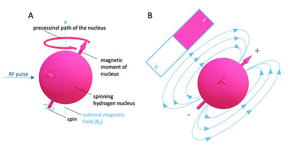
Figure 2: MR active nuclei and spin of 1H
© Anton Windfelder
The gyromagnetic ratio γ0(constant and discrete value for each MR-active nucleus) combined with the known strength of the external magnetic field B allows the determination of the precession frequency ω0 (speed of precession).
This is the Lamour equation:
ω0 = γ B0
It states that an MR-active nucleus's precessional frequency ω0 is proportional to the externally applied magnetic field B0 . It further implies that discrete imaging of MRactive nuclei is possible.
Because of the parallel alignment of the nuclei with B0 and their phase coherence after resonance, a macroscopic net magnetization occurs that precesses in the direction of B0 (typical the transverse plane in a superconducting MR scanner). This macroscopic net magnetization is measurable with a simple conductor (receiver coil, Figure 3A). According to Faraday's law, the sample's rotating net magnetic field induces an electric current in the conductor. This voltage is the actual MR signal (Figure 3A). The frequency of precession determines the MR signal's frequency, and the field strength of the net magnetic moment determines the amplitude of the MR signal. When the RF pulse stops, also resonance stops, and the nuclei (protons) flip back to B0 . The net magnetic vector chances from a transversal magnetization to longitudinal magnetization and the MR signal fades away as free induction decay (FIT) (Figure 3A). This process is called relaxation. If the observer is in the "rotating frame of reference" and precesses with the protons, the relaxation appears as a simple flip from transversal to the longitudinal magnetization (Figure 3D). However, if the observer is in the "laboratory frame of reference" and looks from "outside" the MR scanner, the relaxation follows a complicated helical trajectory (Figure 3C). In most cases, it is more convenient to think within the rotating frame of reference, but it is essential to remember that phase coherent precession is still happening.
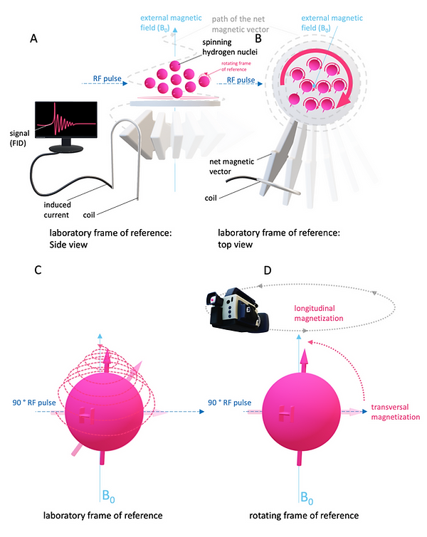
Figure 3: MR Signal and frame of reference
© Anton Windfelder
As a matter of fact, the described MR signal originates from the entire sample (the whole animal or patient) because all protons within B0 are precessing at ω0 (after the RF). This, of course, will not produce a useful MR image. To create a meaningful MR image, it is crucial to limit the nuclear precession to a specific slice within the sample. This is possible by applying a second gradient magnetic field (Figure 4). This secondary magnetic field is a gradient magnetic field, which linearly (and therefore predictably) changes its field strength. The combined net field strength of both fields results in the precession of nuclei limited to a specific area with the “correct” amount of field strength for ω0 (Figure 4). The slope of the magnetic field (called slice selection gradient or Gz ) determines the thickness of the selected slice. All nuclei outside this slice don't precess at the right frequency and consequently don't contribute to the MR signal (Figure 4).
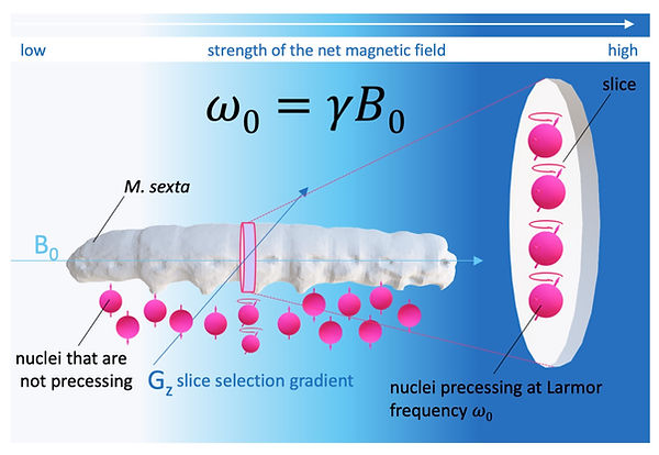
Figure 4: Slice Selection in MRI
© Anton Windfelder
The next step is the MR signal's spatial encoding along the x- and y-axis within the slice. In principle, multiple oblique gradient magnetic fields are thinkable for spatial encoding analogous to how spatial encoding is done in CT (see CT). In fact, the very first MR image of the human head was produced via back-projection, but modern MR systems use a different approach for spatial encoding. Here only two additional discrete gradient magnetic fields are applied (one within the x- and one within the y-axis (Figure 5A). The gradient magnetic field along the x-axis is called the frequency encoding gradient (Figure 5A). This linear gradient interacts with the slice's precessing net magnetic vector so that the frequency of the precession changes along the x-axis. The spatial information of the MR signal is now frequency-encoded. However, the encoding of the spatial information along the y-axis is more complicated. In principle, a second discrete gradient (called phase encoding gradient) changes the phase of the precessing nuclei within the excited slice (Figure 5). But the MR system cannot measure a phase difference directly. Hence, the phase difference along the y-axis is also measured as a pseudo-frequency. Therefore, multiple gradient magnetic fields with different slopes must be applied (Figure 11). Each gradient field results in an MR-signal, which is phase-shifted in comparison to the previous MR-signals. The MR- raw data is stored in a matrix or spreadsheet called “k-space”. Here, the phase-shifted MR-signals are compared and “translated” into pseudo-frequencies via fast Fourier transformation (FFT). Fast Fourier transformation now uses the spatial frequency from frequency encoding and the spatial frequency (pseudo-frequencies) from phase encoding to calculate each frequency's specific amplitude and allocates it to its unique location within the slice (Figure 5A). High amplitudes are depicted as bright voxels (within the grayscale), low amplitudes are represented as dark voxels (within the grayscale) (Figure 5B - F). The number of voxels (3D pixels) in an MR image is determined by how many lines are filled in k-space (how many different phase encoding gradients have been used) and how many data points are in each line (how many frequencies can be distinguished).
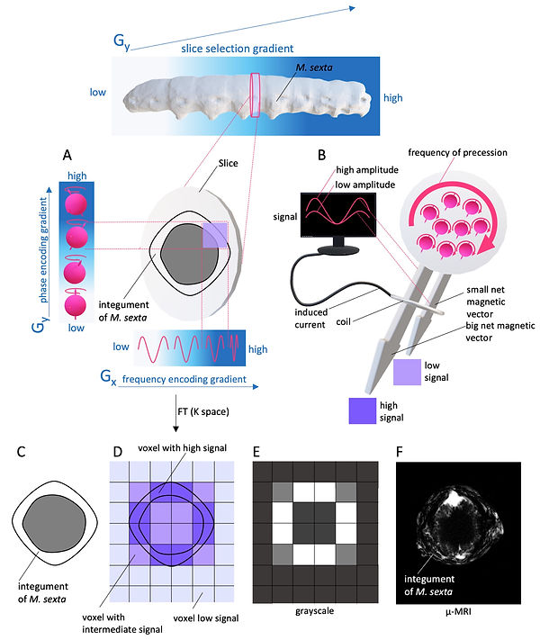
Figure 5: Spatial encoding and signal strength in MRI
© Anton Windfelder
How is image contrast generated in MRI?
One advantage of MRI is that it can image multiple contrast features of different tissues. In general, fat and water (normal biological tissue) are the two extremes on the contrast scale, and each can be emphasized or weighted differently. Accordingly, tissue with intermediate contrasts has mixed features of fat or water. The two main contrast mechanisms in MRI are called T1 recovery and T2 decay. To understand these two contrast tools, it is crucial to understand what happens to the excited nuclei (protons) after withdrawing the RF pulse. According to thermodynamics, absorbed energy from the RF pulse must be re-emitted.
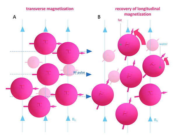
Figure 6: Image contrast: T1 recovery
© Anton Windfelder

Figure 7: Image contrast: T1 recovery (difference of fat and water)
© Anton Windfelder
One way how spins emit energy is to their general surrounding environment or lattice (Figure 6). This process is called spin-lattice energy transfer. During this process, the spins relax and return to B0 (longitudinal magnetization). The time it takes to reach the initial longitudinal magnetization is a tissue-specific inherent parameter called “T1 recovery time” (Figure 7). To be precise, it is the time it takes to regain 63 % of the initial longitudinal magnetization (Figure 7). Fat has low inherent energy and can absorb energy very efficiently. On the other hand, water has high intrinsic energy and cannot transfer energy quickly to the surroundings. Moreover, the molecular motion of fat is close to the Larmor frequency, allowing quick energy transfer. In contrast, water's molecular motion is much too fast for a match with the Larmor frequency. Because fat has a short T1 recovery time and water has a long T1 recovery time, the contrast difference among them is correspondingly high. The most common T1 contrast agents are gadolinium-based (Gd). In contrast to CT, contrast agents in MRI are not imaged directly. Gadolinium has seven unpaired electrons and has a large magnetic moment. In addition, it is highly hydrophilic. Fluctuations in the magnetic moment of gadolinium occur near the Lamour frequency (Figure 8). This fluctuations induce tumbling of water molecules nearby of Gd also close to Larmor frequency, which dramatically shortens their T1 recovery time (Figure 8A). However, protons in fat molecules are unable to get close to Gd and are therefore excluded from T1 shortening.
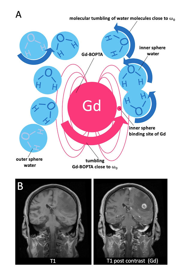
Figure 8: Paramagnetic relaxation enhancement of inner and outer sphere water due to gadolinium and non-small cell lung carcinoma (NSCLC) metastasis with contrast uptake.
© Anton Windfelder
Another way how spins re-emit energy is due to spin-spin interactions. Here the spins lose phase coherence (Figure 9). The time it takes to lose 63 % of the transverse magnetization due to phase coherence is called T2 decay time (Figure 10). Once again, this time is intrinsic and tissue-specific. Protons in fat are densely packed, and hence spin-spin interactions are common in fat, which results in a short T2 decay time for fat. In contrast, protons in water are widely scattered apart, which results in rare spin-spin interactions and, therefore, a long T2 decay time for water. Since this time the loss is measured, water has the greater signal in comparison to fat in T2 weighting (Figure 10).
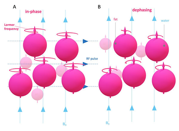
Figure 9: Image contrast: T2 decay
© Anton Windfelder
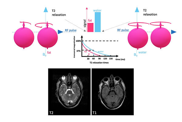
© Anton Windfelder
Figure 10: Image contrast: T2 decay (difference of fat and water)
T2 or T1 weighted images are generated via pulse sequences. As an example, we will discuss here a frequently used conventional spin-echo sequence (CSE) for T1 or T2 weighting (Figure 11). The fundamental problem of signal loss due to loss of phase coherence is solved in CSE due to a second 180° RF pulse, which refocuses the spins and produces a so-called spin-echo (Figure 11). This technique allows each tissue to reach its respective T1 recovery or T2 decay time. CSE sequences are the gold standard in terms of image contrast or weighting. The disadvantage of CSE is the long scan time. Extrinsic parameters, which allow a clear image weighting (T1 or T2) in pulse sequences, are the repetition time (TR) and time to echo (TE). TR is the time between the 90° RF pulses, and TE is the time from one 90° RF pulse to the midpoint of the echo after the 180° RF pulse. The time between the start of the 90° RF and the start of the 180° RF pulse is called Tau (two times Tau results in TE). Although T1 recovery and T2 decay are closely related in time, they do not run entirely parallel (Figure 12). This can be exploited to generate T1- or T2-weighted images. For T1 weighting, a short TR is engaged. After some “preparatory pulses”, steady-state with partial saturation is accomplished, and the short TR allows high T1-contrast separating fat and water. On the other hand, a short TE is employed to minimize T2 contrast. For T2 weighting, a long TR (to reduce T1 contrast) and a long TE are used. The long TE accentuates T2 contrast by providing enough time for the net magnetic vector to decay in fat and water.
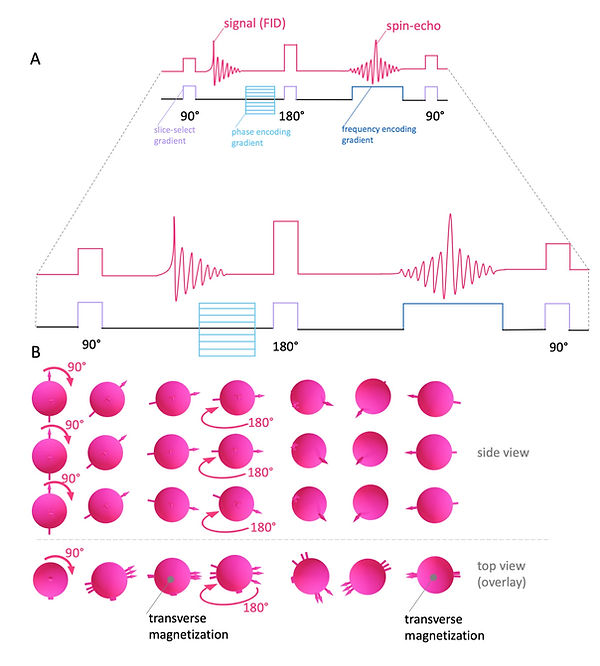
© Anton Windfelder
Figure 11: Conventional spin echo pulse sequence and rephasing 180° RF pulse

© Anton Windfelder
Figure 12: Temporal context of T2 decay and T1 recovery
The contrasting behavior of fat and water-based protons in MR imaging allows the specific suppression of one of these tissues. In most cases, the unwanted signal of fat is avoided in this way. In particular, after the application of contrast agents (T1 contrast agents) in T1 weighted images, it is essential to prevent high ambiguous signal intensities due to fat tissue. In general, the suppression of fat signal (fat-sat) can be obtained by short tau inversion recovery (STIR) sequences or due to chemical presaturation techniques like chemical shift selective sequences (CHESS). However, only CHESS sequences suppress the specific signal of fat tissue, whereas STIR sequences only suppress signals with short T1, which is typical for fat but also for contrast agents.
In chemical shift fat saturation, the difference in precessional frequency of water and fat is exploited. This phenomenon is called chemical shift. Electron clouds from methylene groups of fatty acids induce a higher precessional frequency of nuclei in fat than in water. The difference in precessional frequency of fat and water is a function of magnetic field strength (B0). Most clinical MR experiments are done at 1.5 T, and here protons in fatty acids precess 224 Hz faster than protons of water (Figure 13A). For fat saturation, a narrow-bandwidth 90° fat-specific presaturation RF pulse is given to the entire FOV (Figure 13). This is followed by a conventional 90° RF pulse at (ω0) (Figure 13) . This flips the magnetic moments of fat nuclei into saturation (180°), and the remaining water nuclei into transversal magnetization (Figure 13B). Thereby, only water nuclei produce a signal without suppressing the signal of the T1 extracellular contrast agents.
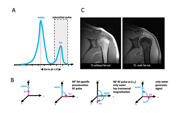
© Anton Windfelder
Figure 13: Chemical shift selective sequences (CHESS) for fat saturation (Fat-Sat)
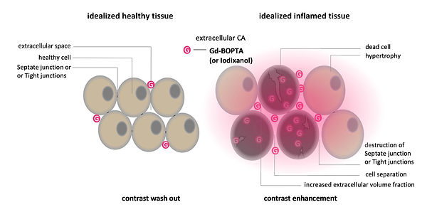
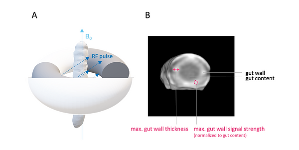
For the phenotyping of colitis-like lesions in Manduca sexta, we used the T1 extracellular contrast agent Gd-BOPTA. The infection-induced necrosis results in an expansion of the extracellular volume fraction compared to healthy uninfected tissue (Figure 14 and Video 1). The pharmacokinetics of extracellular fluid agents like Gd- BOPTA are exploiting these differences in volume fractions. The larger, easily accessible extracellular volume in an inflamed lesion causes a concentration of the contrast agent called hyperenhancement (Figure 14 and Video 1). However, this is not the case in healthy tissue, which results in rapid washout of the extracellular agent or in non-enhancement (Figure 14, and Video 1). Through the process of hyperenhancement, most pathologies, including cancer and inflammation, can be identified, which illustrates the great value of contrast media for diagnosis (Figure 8). For the phenotyping of colitis-like lesions in M. sexta, the well-established mammalian imaging findings of gut inflammation: post-contrast maximal gut wall thickness and normalized post-contrast maximal gut wall signal strength have been used (Figure 15).
© Anton Windfelder
Figure 14: Mode of action: extracellular contrast agents in MRI
© Anton Windfelder
Video 1: Mode of action: extracellular contrast agents in MRI
© Anton Windfelder
Figure 15: M. sexta in MR imaging and imaging findings for phenotyping of colitis-like lesions
